
Learn how to use the HAL Robotics Framework.
• documentation home• decode
• Grasshopper SDK
• back to main site
• issues and bugs
1. Getting Started
1.1. Quick Start
Objective:
In this tutorial we’ll take the shortest route from an empty session to a moving Robot in the HAL Robotics Framework for Grasshopper.
Demo Files:
 Getting Started.gh
Requirements to follow along:
- McNeel’s Rhinoceros 3D and Grasshopper, and the HAL Robotics Framework installed on a PC.
- A basic knowledge of Rhinoceros 3D and Grasshopper are highly recommended.
Background:
The HAL Robotics Framework is a modular software library that simplify the modelling, programming and simulation of processes involving industrial machines. The client for McNeel software gives you access to the vast majority of the Framework’s functionality from within Grasshopper, a visual programming environment that runs within Rhinoceros 3D.
How to:
Once you’ve opened Grasshopper and logged in to the HAL Robotics Framework to access your licenses you should be presented with a blank Grasshopper canvas and a new HAL Robotics tab at the top your screen. There are plenty of tools within this tab to allow you to program just about any process you want, and other tutorials will look at each of them individually as well as the structure of the interface, but for now, we’re just going to get up and running as quickly as possible.
![]() The new blue HAL parameters should show up in the “Params” tab.
The new blue HAL parameters should show up in the “Params” tab.
![]() The “HAL Robotics” tab contains the components we will use in this tutorial series.
The “HAL Robotics” tab contains the components we will use in this tutorial series.
The first component we’re going to use is the Robot. You’ll find it inside the Cell menu, in the top left of the toolbar. When we place that component on the canvas not much happens. This is because Robot is one of a few special types of component that we’ve developed to extend the default Grasshopper interface. We’ll see what each does as we come across them and they are all covered in a special tutorial so feel free to have a look at that for more detail.
This particular component has an interlocking squares icon ⧉ on the name bar. This indicates that it can be double-clicked to get a pop-up window. If we open that window on the Robot component then we get the Robot Catalog. You can select any Robot you want by simply clicking on it and then the “Select” button. I’m going to choose the IRB 1200 - 0.7m as that’s what I have next to me at the office. Once we’ve made our selection it will pop up into the scene. If you want to change your choice, you can always double click on the component again.
 Double click on the robot component to open and select a robot preset.
 You can also find this component by using the Grasshopper search feature, by double clicking on the canvas and typing “robot”.
 As the default Grasshopper search feature is limited, we added our own component browser allowing you to look for keywords in components, and preview filtered results. To access this utility, you can use the Documentation component in the Help menu, or via the “HAL>Help>Documentation” menu of the Grasshopper window.
We now have a Robot, but we’re almost always going to need a Tool, also called end-effector as well, so I’m going to add a Tool component, again from the Cell menu. We assume that you will want to create your own Tools so this catalog component contains only a few options to get you started. The creation of Tools is covered in future tutorials (1,2,3) so please have a look at those for more information. I’m going to select the extruder because I know it’s about the right size for this Robot.
 Double click on the “Tool” component to open and select a tool preset.
Once we have a Robot and a Tool in the scene, we need to connect the two together. We do that using the Attach component. We will see that once we’ve assigned the Robot component as the Parent and Tool component as the Child, the extruder is attached to the end or Flange of the Robot. That’s all there is to creating our very simple Robot Cell.
We’re going to hide all the components we’ve already added to ensure that we can see what we’re doing as we proceed.
 Attach the robot and the tool mechanisms together using the “Attach” component, then hide all components to free the viewport for the following programming steps.
Now that we have a Robot in the scene, we need to program it. To get started I’m just going to make it follow a curve that I have drawn in Rhino and referenced in Grasshopper. Robots don’t inherently understand geometry so we have to convert this curve into a series of Targets for the Robot to follow. We can this with the Target component under the Motion menu. When we place the component on the canvas you should see that its key input is a list of Frames but this component also has a black band at the bottom which says “Template 1/n”. This is the second new component type we’ve come across. Template components can be right-clicked upon and their shape changed. In this case you can see that there are a few different ways of creating Targets. We’ve got a curve as input so we’re going to choose Target from Curve. There are a number of things we can change here but to keep things simple we’ll keep the defaults and just assign the curve in the Curve input. You should see a number of Targets appear in the viewport. The exact number and pattern, of course, will vary according to the curve you’re using.
 You can generate curves in Grasshopper or use the “Curve” parameter to register a Rhinoceros curve from which targets will be generated.
Please note that Targets can be edited and transformed in any way you want, and that you can also use Grasshopper planes to create Targets from scratch. Please see the dedicated tutorials in the Motion section of this documentation).
Now that we have some Targets, we need to actually instruct the Robot to move through them. We do this using the Move component which is found in the Procedure menu. There are plenty of options to control how a Robot gets to these Targets and they are discussed in detail in future tutorials (1,2). The bare minimum is to assign our Targets to Move and there we have a Procedure ready for Execution. Again, I’m going to hide the components other than Move to keep things simple on screen.
 Use the “Move” component to generate a robot motion through the generated targets.
Now that we have a Robot and a Procedure, we need to link the two together. In the HAL Robotics Framework, as with your real Robot, the entity that interprets programming to actuate a machine is a Controller. We can get a Controller from the Cell menu. We can see that this also has the interlocking squares icon ⧉ and therefore can be double-clicked to get a pop-up window. From this Controller Catalog you can choose the Controller you are using as you did with the Robot. Please note, you will need the extension for any brand installed to be able to load their Controllers. If you didn’t install any extensions you can continue with the Generic Controller for now and install the brand-specific extensions from the HAL Robotics Framework Installer later. The Robot we have here uses an IRC5 Compact V2 so I’m going to pick that. You can configure the complete setup of your Controller and we have a separate tutorial on that but for now I’m going to “Configure” with the defaults. The position and visual representation of the Controller is of little interest in this case so I’m going to hide it immediately. With the Controller in place we can assign the Robot and Procedure to link the two together.
 Double click on the “Controller” component to open and select a controller preset, then plug the robot and tool as the controlled mechanism, and the motion through targets as the procedure to be assigned to the mechanism.
Now, of course, we want to see whether the Robot can make it round our curve without issue. This is referred to as “Solving” and is done using the Procedure Solver component in the Simulation menu. With that component in place we can assign the Controller and toggle the Solve Boolean to true. This will start the solving and any issues, errors or notification will be output under Notifications. If we now want to visualize that solved Procedure then we can add the Execute component to the end of our chain from, again, the Simulation menu. This should come with its Execution Control pre-attached but if it doesn’t you can find the Execution Control under the Simulation menu as well. Once the Solution is assigned to the Execute component we’re ready to hit Play and watch our Robot make its way around the curve. If your Robot is moving, congratulations, you’ve completed your first session with the HAL Robotics Framework for Grasshopper.
 The simulation is split into two steps: the “Solver” computes the robot behavior, and the “Execute” component displays the computed solution.
1.2. Interface Overview
Objective:
In this tutorial we’ll take a look at the layout HAL Robotics Framework components in Grasshopper.
Requirements to follow along:
- McNeel’s Rhinoceros 3D and Grasshopper, and the HAL Robotics Framework installed on a PC.
Background:
The HAL Robotics Framework for Grasshopper installs a new tab within the Grasshopper UI called HAL Robotics. You will know that the Framework is installed if you can see the HAL Robotics tab and a number of blue hexagonal parameters components on the Params tab.
How to:
In the Params tab you will find a number of HAL Robotics Framework parameters. These are all in blue hexagons and may come in useful for keeping your documents organized. The parameters panels are organized in the same way as the HAL Robotics tab, as we’ll see shortly, with the addition of all of these units which can be used to ensure you use the units most appropriate to your way of working regardless of the units of your model space.
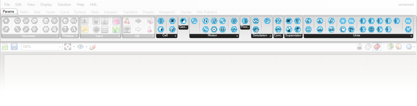 The HAL parameters are shaped as blue hexagon.
Within the HAL Robotics tab, you will see a set of panels. These are ordered and organized to guide you through the process of setting up your processes in the HAL Robotics Framework.
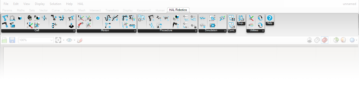 The HAL Robotics tab is ordered following the software workflow, from the robot cell modelling, to the procedure execution utilities.
Cell
The Cell panel covers everything you’ll need to build up a virtual version of your robotic Cell. This includes Robot, Positioner and Tool presets, as well as the components required to build your own Mechanisms, Parts, set up your I/O Signals and assemble all of these into a complete digital system through a Controller.
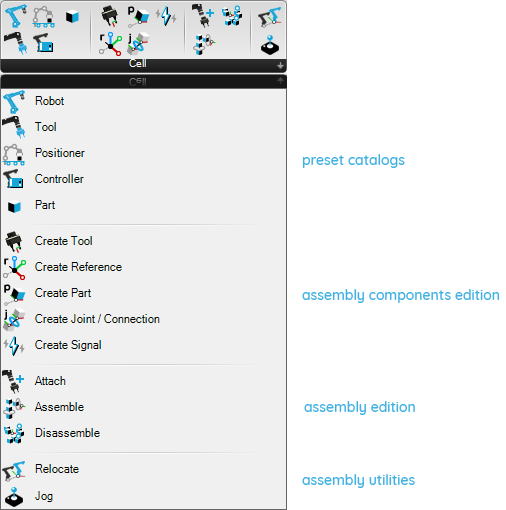
The “Cell” panel contains everything to model the hardware of a robot cell.
Motion
The Motion panel contains all the components to create and manipulate Targets and control how your Robots are going to move towards those Targets by specifying the Speed, Acceleration, Blend and Kinematic Settings.
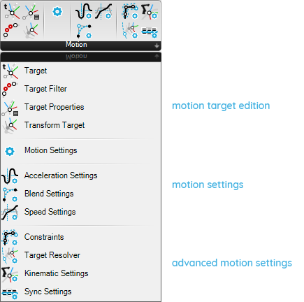
The “Motion” panel contains everything to fine tune a robot motion.
Procedure
The Procedure panel is where you’ll find all the tools necessary to program your machines. This includes Move, Wait and Signal Change Actions as well as utilities for changing Tools at runtime, manipulating Parts and Combining these into a Procedure ready to Simulate.
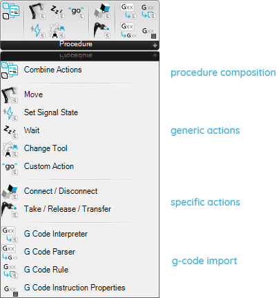
The “Procedure” panel contains the different actions forming a robot procedure.
Simulation
The Simulation panel contains everything you need to Solve and Execute a Simulation of your Procedures.
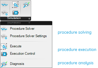
The “Simulation” panel contains the utilities to compute and visualize simulated robot procedures.
Control
The Control panel is where you’ll find components to get your Procedures out of the digital world and onto your real machines. This includes functionality such as Exporting and Uploading code.
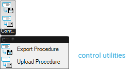
The “Control” panel contains utilities to transform your simulation into executable robot code.
Utilities
The Utilities tab contains useful tools such as Frame creators which will enable you to input or output frame data in any standard formalism.
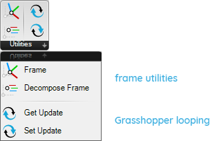
The “Utilities” panel contains various utilities.
Help
The Help panel contains the Documentation component and other tools to help you look up information about the software.
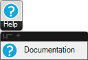
The “Documentation” component can be dropped on a component to visualize its documentation.
1.3. Components
Objective:
In this tutorial we’ll look at the component variations and patterns added to HAL Robotics Framework components in Grasshopper.
Requirements to follow along:
- McNeel’s Rhinoceros 3D and Grasshopper, and the HAL Robotics Framework installed on a PC.
How to:
On any given HAL Robotics Framework component, you will notice a few recurring patterns and symbols in the names of inputs and outputs. These patterns can be used individually or combined on a single parameter. The Create Part component is a good example of all of these.
-
→ Name - An arrow ( → ) preceding an input name means that the input is mandatory. Component will not compute until data is provided to every mandatory input.
-
[Name] - Square brackets [ ] around the name of an input or output mean that the data will be treated as a list or collection.
-
{Name} - Curly brackets { } around the name of an input or output mean that the data will be treated as a Grasshopper DataTree.
-
Name (unit) - A name followed by a unit in brackets e.g. (mm) or (rad), means that the input will be treated in a specific unit. These units can be changed by right-clicking on the input, hovering over Unit and selecting the unit you prefer to use. You can assign a textual expression to these inputs and it will be calculated for you e.g. 3m + 35mm.
To help keep the interface and number of components manageable we have introduced 3 new modes of interaction with Grasshopper components. Components that feature each new interaction mode can be identified easily.
-
Windowed Components a.k.a. Pop-up Components, such as the Robot preset component, feature two interlocking squares ⧉ in their name. You can double click on these components to get a pop-up window with additional component inputs. This could be a catalog of available Robot or Controller presets, or an overview of Procedure execution progress.
-
Overloaded Components, such as the Create Reference component, can be recognized by their black bar at the bottom which states Shift + ↕ (1/2), or similar. Overloads of a component all perform the same function, such as creating a Reference, but are designed to simplify components for typical use by keeping advanced inputs out of the way until you need them.
-
Templated Components, such as the Frame component, can be identified by their black bar at the bottom which states Template 1/3, or similar. Templates are a means of grouping components that create similar objects or use different construction methods. For example, in the case of Frame, the templates represent different formalisms for frame creation such as Euler, Quaternion etc. Similarly, in the Create Target component, templates all create Targets but use different inputs e.g. from a Frame, from Joint Positions or from a Curve.
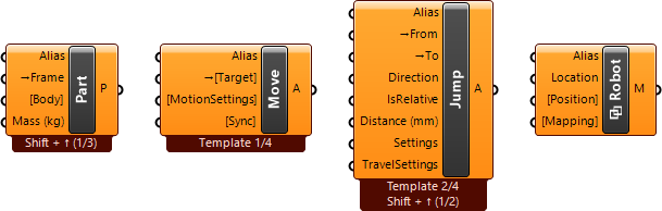
The various parameter decorations and shape-changing component features listed above are visible on these four components.
1.4. Documentation Component
Objective:
In this tutorial we’ll look at the Documentation component and how it can help you discover functionality within the HAL Robotics Framework for Grasshopper.
Requirements to follow along:
- McNeel’s Rhinoceros 3D and Grasshopper, and the HAL Robotics Framework installed on a PC.
Reading or watching the Component Variations tutorial is highly recommended.
How to:
The Documentation component can be accessed through the HAL menu under Help -> Documentation or via the Help panel in the HAL Robotics tab of Grasshopper. You can drag this component onto an existing component to display its documentation, or if you instantiate the component on the canvas, you will be presented with a list of all the available HAL Robotics Framework components.
Using the search bar at the top of the window you can look for functionality that interests you. For example, if you type “speed” and trigger the search by hitting the enter or space key you will see a list of components which use the word “speed” in their title or description. The first option presented should be the Speed Settings. By selecting that component, if it isn’t already, you will see the component layout at the bottom of the window with descriptions of each input and output, as well as a series of tabs which will show the different overloads of the component. From here you can add the component to your current document by clicking “add to document” or close the window to cancel. This same functionality is extended to many other Grasshopper libraries and plugins which can be activated in the Libraries slide-out on the left-hand side of the window.
You can browse the various component overloads by using the tabs at the bottom of the window, if any.
It is possible to use the HAL Documentation browser with all Grasshopper components, including plugins.