
Learn how to use the HAL Robotics Framework.
• documentation home• decode
• Grasshopper SDK
• back to main site
• issues and bugs
2. Cell Setup
2.1. Insert a Robot
Objective:
In this quick tutorial we’ll take a look how to insert a Robot preset into your decode scene.
Requirements to follow along:
- HAL Robotics decode installed on a PC. See Installation if you need to install the software.
- An open project
How to:
On the Scene screen, select Robot from the Item Type selector at the very top, then click +. The From Preset Creator will allow you to select a Robot from our catalogue.
Select the Preset Step and the Robot catalogue will pop-up. Double-click on the robot you want to load to choose it. If the Robot you want isn’t listed, look for the Scan Online Content button in lower left-hand corner which will list all the available Robots and download whichever one you choose. There are plenty to choose from so it may take a few seconds to list them all. Next time you load the catalogue, your offline Robots will be listed.
If you need to set the Location of the Robot, choose that Step and adjust accordingly. The Reference setting can be used to adjust whether you want to define a Location relative to the Scene’s origin, or the element to which the Robot is attached, its Parent.
Once you are happy with the Robot’s setup click ok in the upper right corner to return to the Scene screen.
 There are lots of robots to choose from in the online catalogue.
2.2. Create a Tool
Objective:
In this tutorial we’ll create a simple Tool for your decode scene.
Demo Files:
 Tool.stl
Requirements to follow along:
- HAL Robotics decode installed on a PC. See Installation if you need to install the software.
- An open project
- A Robot in the Scene
Background:
More often than not you will need a Tool or End Effector in your Cell to undertake a process. The Tool could be anything from a welding torch to a spindle or even something as simple as a pen. Tools can be attached to the end of a manipulator like a Robot or stationary with a Robot bringing the Part to the Tool.
How to:
From the Scene screen, select the Robot onto which you want to attach the Tool. That will enable the Item Type selector to list Tool as an option. N.B. Stationary Tools will be enabled in a future update. Click + and you’ll start creating a Tool.
The From Preset Creator will allow you to select a Tool from our catalogue. If one of those works for you, you can skip to settings the Location below, but with the enormous variety of Tools in the world and even the ease with which one can create an entirely unique, custom Tool for a process, chances are good that you will need to model your own Tool. To do that, select From Components in the Creator selector and you’ll see the Assemble Step appear.
 The Tool editor with the From Components Creator selected.
Opening the Assemble Step will generate a mini-Scene which represents your Tool. A Tool will always be composed of at least one Part which acts as its base, and one endpoint which acts as the tool centre point (TCP).
Start by adding a Part and you’ll get a whole new Creator embedded. There are lots of options here to explore but the most common workflow is likely to From Geometry and importing your Part Body From CAD File. There first editable Step therein is CAD File which will allow you to select the CAD file which contains your Tool’s geometry. To keep things simple, it’s worth ensuring that the base of that geometry is at the origin of the file you’re importing but you can adjust that with the Location if needed. The next few Steps will work on their own to import that geometric data and convert into our own formats for optimal performance. The rest of the Part settings are optional and should be self-explanatory. Click ok on the Creator to finish creating that Part.
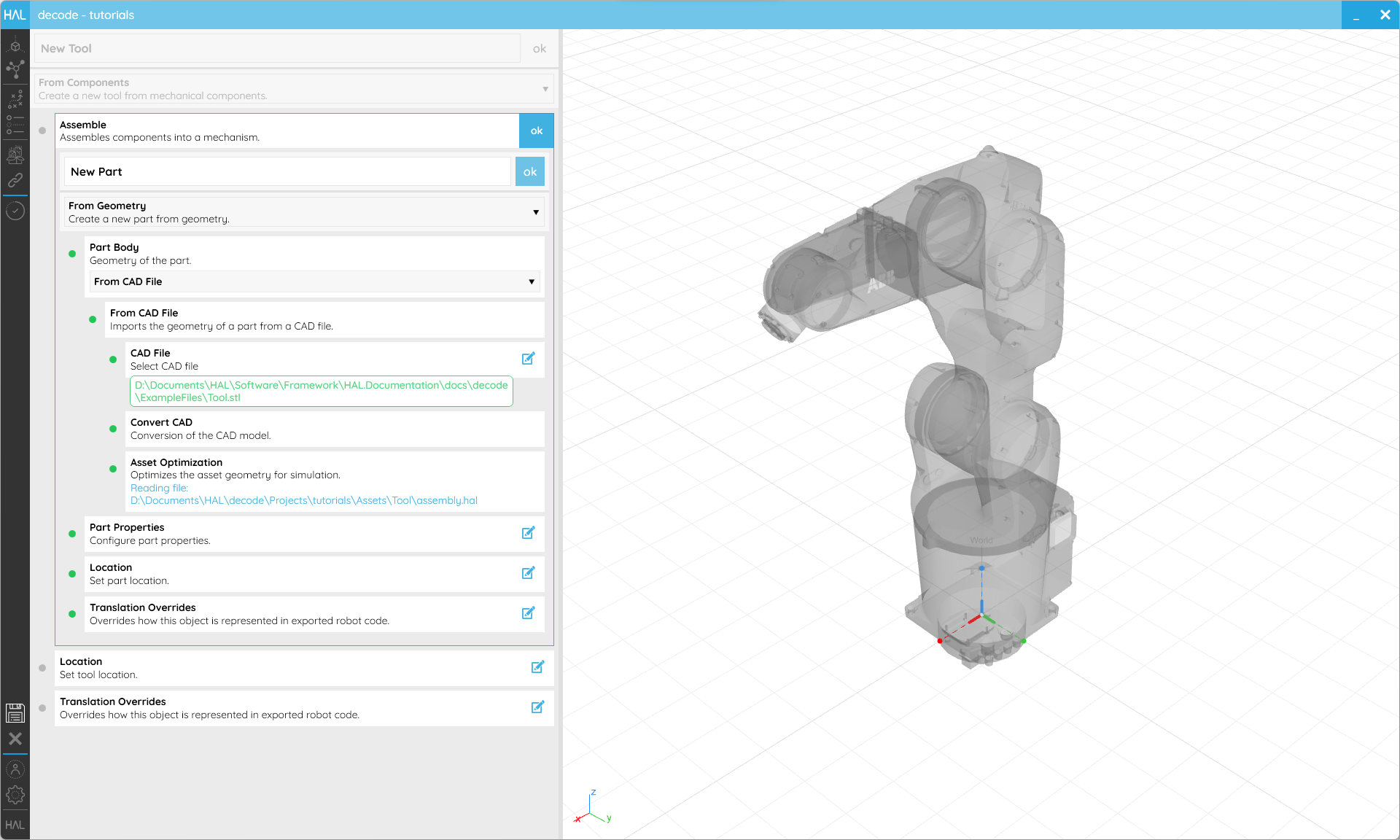 The Part Creator in From Geometry mode allowing the importing of a CAD file to act as the Tool’s geometry.
Now select your Part, and you can add an Endpoint to it. The only settings here are for the Location of that Endpoint which will act as the TCP. This is most easily set relative to its Parent as a Reference and we recommend that the Z axis of TCPs point out of the Tool, following the co-ordinate system flow of the Robot itself. Click ok on the Creator to finish creating that Endpoint and then on ok again to complete the assembly.

You will see the position of the TCP in the live preview.
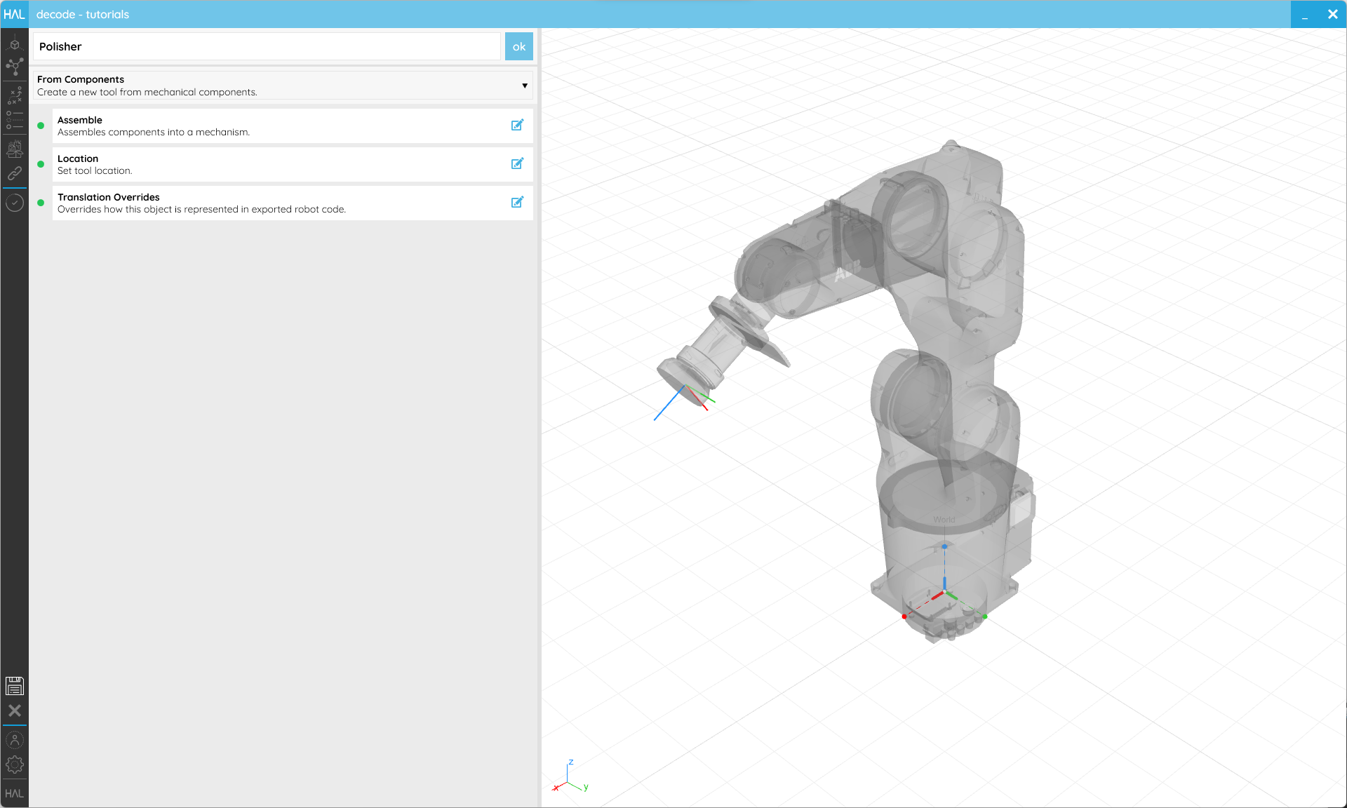
As standard, the Tool’s base will be attached to the Robot’s flange, or endpoint. Setting the Location allows you to offset that attachment point if you need to.
The Translation Override Step will allow you change how the Tool is exported into Robot code.
Once you are happy with the Tool’s setup, ensure the name makes it easy to identify and click ok in the upper right corner to return to the Scene screen.
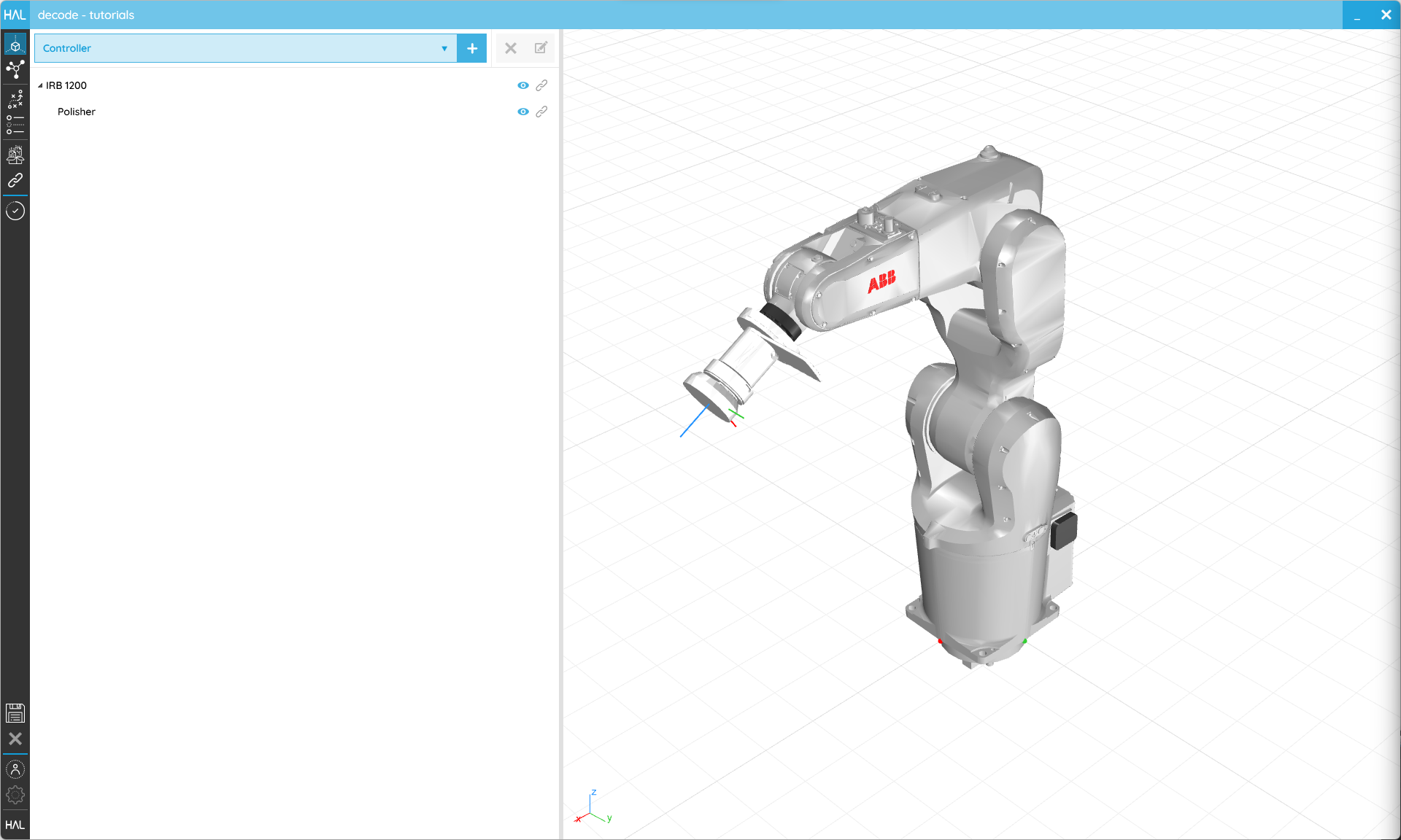 The Tool should appear attached to our Robot and show the location of our TCP.
2.3. Create a Reference
Objective:
In this tutorial we’ll see how to create References for your decode scene.
Requirements to follow along:
- HAL Robotics decode installed on a PC. See Installation if you need to install the software.
- An open project
Background:
References are useful because they allow us to specify Targets relative to something other than the world or the base of the Robot. This means that they can be recalibrated in the real world without the need to regenerate a Toolpath or Procedure. They can also be connected one onto another to create a logical hierarchy of elements that can be moved as one.
How to:
From the Scene screen, select the Reference onto which you want to attach your new Reference, or click anywhere in the white space to clear your current selection. You can always drag and drop References onto each other to restructure your Scene later. Either of those states will enable the Item Type selector to list Reference as an option. Click + and you’ll start creating a Reference.
The From Location Creator will allow you to set its Location and Translation Overrides, both of which should be familiar to you by now. If not, please refer back to the tutorials above for more details.
Once you are happy with the Reference’s setup, ensure the name makes it easy to identify and click ok in the upper right corner to return to the Scene screen.
 References can be used to relocate or calibrate Parts and CAD Models, or structure your Scene.
Next:
Take a look at the next tutorial on creating Parts to learn how to add geometry to your References.
2.4. Create a Part
Objective:
In this tutorial we’ll see how to add Parts to your decode scene.
Demo Files:
Requirements to follow along:
- HAL Robotics decode installed on a PC. See Installation if you need to install the software.
- An open project
- Reading the Create a Reference tutorial is highly recommended.
Background:
Parts serve two roles in decode and come in two variants. Firstly, Parts can be used to populate your Cells with environmental elements such as pedestals, tables or tool holders which can in turn be used as References for your Toolpaths. They can also be used as the basis geometry for Toolpaths, e.g. following edges or surfaces. When we import Parts for the environment, we optimise them for performance. To retain all the geometric data and therefore enable the latter use, use a CAD Model instead. Both are grouped here because the settings and workflow are almost identical and we’ll use Parts as a general term for both below.
How to:
From the Scene screen, select the Reference onto which you want to attach your new Part, or click anywhere in the white space to clear your current selection. You can always drag and drop Parts onto each other to restructure your Scene later. Either of those states will enable the Item Type selector to list Part and CAD Model as options. So we can reuse it in later tutorials, let’s opt for the CAD Model now and use our Wobbly Block example file. Click + and you’ll enter the editor.
The From Geometry Creator will allow you to select a CAD File, Location and Translation Overrides, all of which should be familiar to you by now. If not, please refer back to the tutorials above for more details.
Once you are happy with the Part or CAD Model’s setup, ensure the name makes it easy to identify and click ok in the upper right corner to return to the Scene screen.
 Parts can be used as environmental context whilst CAD Models are useful to extract geometric data for Toolpaths later.
2.5. Create a Controller
Objective:
In this tutorial we’ll look at how you can create and configure a virtual Controller to match your real Controller in your decode scene.
Requirements to follow along:
- HAL Robotics decode installed on a PC. See Installation if you need to install the software.
- An open project
- A Robot in the Scene is recommended
Background:
Industrial Controllers are typically comprised of core functionality, such as the ability to run a program, extended through optional extras, like communication protocols or multi-Robot support. To ensure that we only try and interact with your real Controller in a way that is compatible, be it through a network or with exported code, we have added a means to configure your Controller. The constituent parts of this are:
a. Controller - this is essentially a computer to which your Robot and Signals are connected.
b. Capabilities - these are how we organize what a Controller can do and draw parallels between different manufacturers’ Controllers. Capabilities are things like the ability to Upload code to the Controller from a PC or the ability to read the values of Signals remotely.
c. Subsystems - these are similar to the options you have in your Controller. They are the actual software modules that implement different Capabilities.
How to:
All of these different parts are best explored with concrete examples so let’s create a Controller and look at how we can configure it. From the Scene screen, select the Reference onto which you want to attach your new Controller, or click anywhere in the white space to clear your current selection. Either of those states will enable the Item Type selector to list Controller as an option. Click + and you’ll enter the editor.
There is only one Creator available here. Select the Preset Step and the Controller catalogue will pop-up. Double-click on the Controller you want to load to choose it. If the Controller you want isn’t listed, look for the Scan Online Content button in lower left-hand corner which will list all the available Controllers and download whichever one you choose. Next time you load the catalogue, your offline Controllers will be listed.
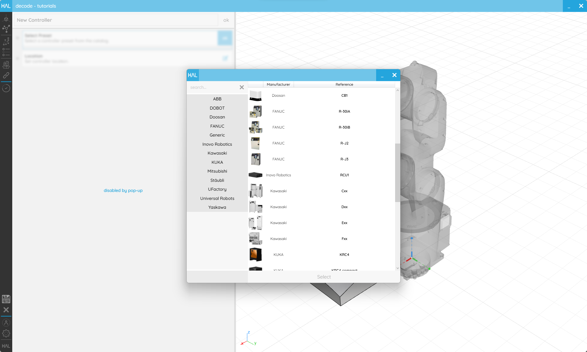
There are Controllers from all our supported manufacturers in the Controller catalogue.
For this example, we’re going to use the IRC5 Compact V2 but you will find details for any other manufacturer’s Controllers in the manufacturer-specific documentation. When we select a Controller, if there is anything to configure, a configuration page will pop-up.
The first thing we’ll see at the top is the system version. In the case of ABB this is the RobotWare version but for KUKA this would be KUKA System Software or in Universal Robots it will be the Polyscope version. It’s important to note that these are version ranges so don’t expect to see every point release listed. By changing the version we’ll change which Subsystems are available. If we switch down to 5.14, EGM will disappear from the options below because it was only introduced in Robotware 6.
The rest of the window is split in two; on the left is Subsystem and Capability selection and on the right is parametrization. In the left-hand column we can see the Capabilities listed with Subsystems that implement that Capability in a drop-down alongside. Let’s look specifically at Upload. By hovering over the name, we can see that the Upload Capability enables Procedure Uploading to a remote Controller. We can also see that there are two subsystems that offer this Capability, PCSDK and Robot Web Services (RWS). RWS is built in to the latest Robotware versions but to use the PCSDK we need the option “PC Interface” on our Controller. If you don’t have that option you can change Subsystem to ensure we use a compatible method to Upload Procedures to your Controller. There may also be circumstances where we don’t have any of the options installed or don’t want access to a Capability for security purposes. In that case we can deactivate the Capability using its toggle. On the right-hand side of the window, we have the inputs to configure our Subsystems. Only active Subsystems are listed so if we deactivate both EGM Capabilities the EGM parameters will disappear. Once we have changed the relevant properties we can select “Configure” to apply our changes. Closing the window without configuring will leave the Controller in an invalid, unconfigured state.

The controller configurator allows you to match the capabilities of your real Controller in the virtual Scene.
If you need to set the Location of the Controller, choose that Step and adjust accordingly. The Reference setting can be used to adjust whether you want to define a Location relative to the Scene’s origin, or the element to which the Controller is attached, its Parent.
Once you are happy with the Controller’s setup click ok in the upper right corner to return to the Scene screen. Controllers are hidden by default in the Scene but can be shown using the eye icon.
2.6. Create a Signal
Objective:
In this tutorial we’ll create a Signal that can be programmed in decode.
Requirements to follow along:
- HAL Robotics decode installed on a PC. See Installation if you need to install the software.
- An open project
- A Robot in the Scene
- A Controller in the Scene
Background:
Electrical Input and Output (I/O) Signals are used to activate or deactivate Tools, trigger actions on remote machines or pass data between Sensors.
How to:
From the Network screen, select the I/O Signals Board into which you want to add your new Signal(s). Signals can’t be moved between Boards later. That will enable the Item Type selector to list a number of different Signals types. Select whichever you need but Digital Outputs are very common so we’ll use that as our example here. Click + and you’ll start creating a Signal of your selected type.
The Configuration Step will allow you to set its upper and lower limits (leave 0 to 24V if you are unsure). TheTranslation Overrides will allow you to use a human readable name within decode but change what’s exported.
Once you are happy with the Signal’s setup, ensure the name makes it easy to identify and click ok in the upper right corner to return to the Network screen.
![]() Translation overrides make it easy to identify Signals without breaking the exported code.
Translation overrides make it easy to identify Signals without breaking the exported code.