
Learn how to use the HAL Robotics Framework.
• documentation home• decode
• Grasshopper SDK
• back to main site
• issues and bugs
3. Programming
3.7. Validation and Simulation
3.0. Procedures
Objective:
In this tutorial we’ll cover the main structure and background of Procedures in decode.
Background:
Procedures are a sequence of Actions to be executed by a Controller. In the Programming screen you’ll find tools to create individual, atomic Actions like Move or Wait as well as ones which generate complex Toolpaths comprised of 10s, 100s or even 1000s of individual Actions.
Each Robot has a main Procedure, always the first in the list, assigned to it. You can add Procedures to a Robot to help you structure your code, but it’s only the main one which will be Solved, Simulated or Exported. Procedures can be added via the + button in the upper right-hand corner of the Programming screen and renamed,or removed through the menu button next to it.
Even complex Toolpaths can be kept to simple Procedures in decode.
3.1. Move
Objective:
In this tutorial we’ll look at the different ways that we can program individual Motions in decode.
Requirements to follow along:
- HAL Robotics decode installed on a PC. See Installation if you need to install the software.
- An open project
- A Robot in the Scene
- A Controller in the Scene
Background:
Motions are the fundamental building block of Robot programming instructing the Robot to go from its current position to somewhere else. We define where a Robot should move using Targets and how they should get there with Motion Settings. We can mix and match Target creation techniques with different Motion Spaces ass we’ll see below.
How to:
From the Programming screen, select the Group into which you want to add your new Move, or click anywhere in the white space to clear your current selection. You can always drag and drop Actions onto Groups or in between other Actions to restructure your Procedure later. Either of those states will enable the Item Type selector to list Move as an option. Click + and you’ll start creating a Move.
There are two Steps here which align with the where and how the Robot moves mentioned above.
There are 2 main ways of creating Targets, both of which are found in the Target Step.
Targets in decode can be edited in Joint or Cartesian spaces.
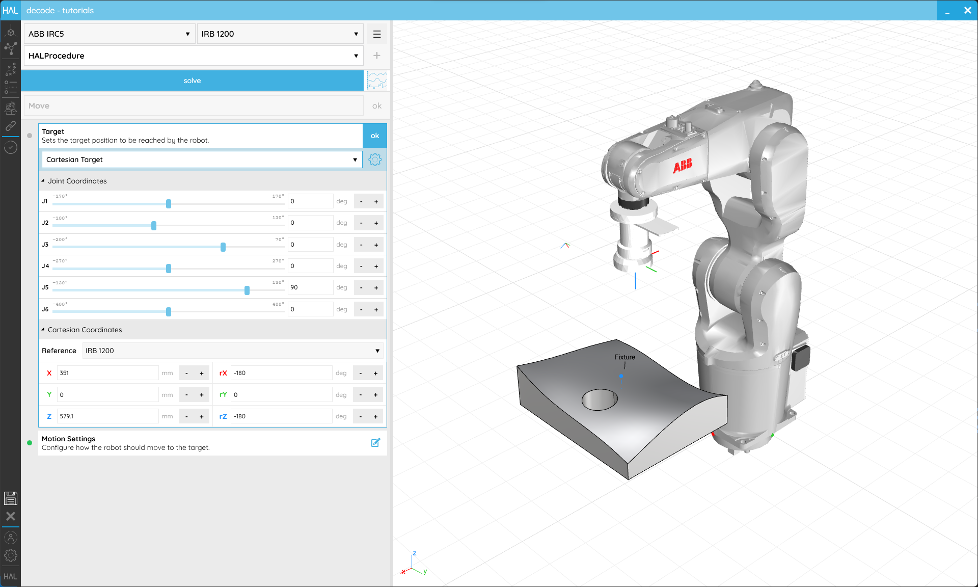
The first way of creating a Target is in Joint space, that is by defining the desired position of each active Joint of your Robot. The list of Positions correspond to each active Robot Joint. As you change these values, you can visualize the final position of our Robot at these Joint positions.
The other way of creating a Target is a Cartesian Target from a Frame. When a Robot moves to a Cartesian Target the active TCP of our Robot will align with the Target’s position and orientation. As you change the values of that Frame you can see our Target move and our Robot moves with it. A Frame is always relative to a Reference which can also be set here. Please take a look at the References tutorial to see how those work.
At the top of the Target Step is a crucial selector. It allows us to specify the Motion Space in which we want to store the Target. N.B. This does not affect how we move to the Target. Selecting Joint Space will mean that we consider only those Joint positions and we ignore the Cartesian Frame. If, for example, you were to change the length of your Tool or the location of a Reference, it wouldn’t matter because these are fixed values for each Joint. Selecting Cartesian Space will mean that we only consider the Cartesian Frame. If, for example, you were to change the length of your Tool or the location of a Reference, we will recompute the values for each Joint to get the Robot into that position.
Either of these Target creation options give exactly the same types of Target so can be used with any Motion Settings.
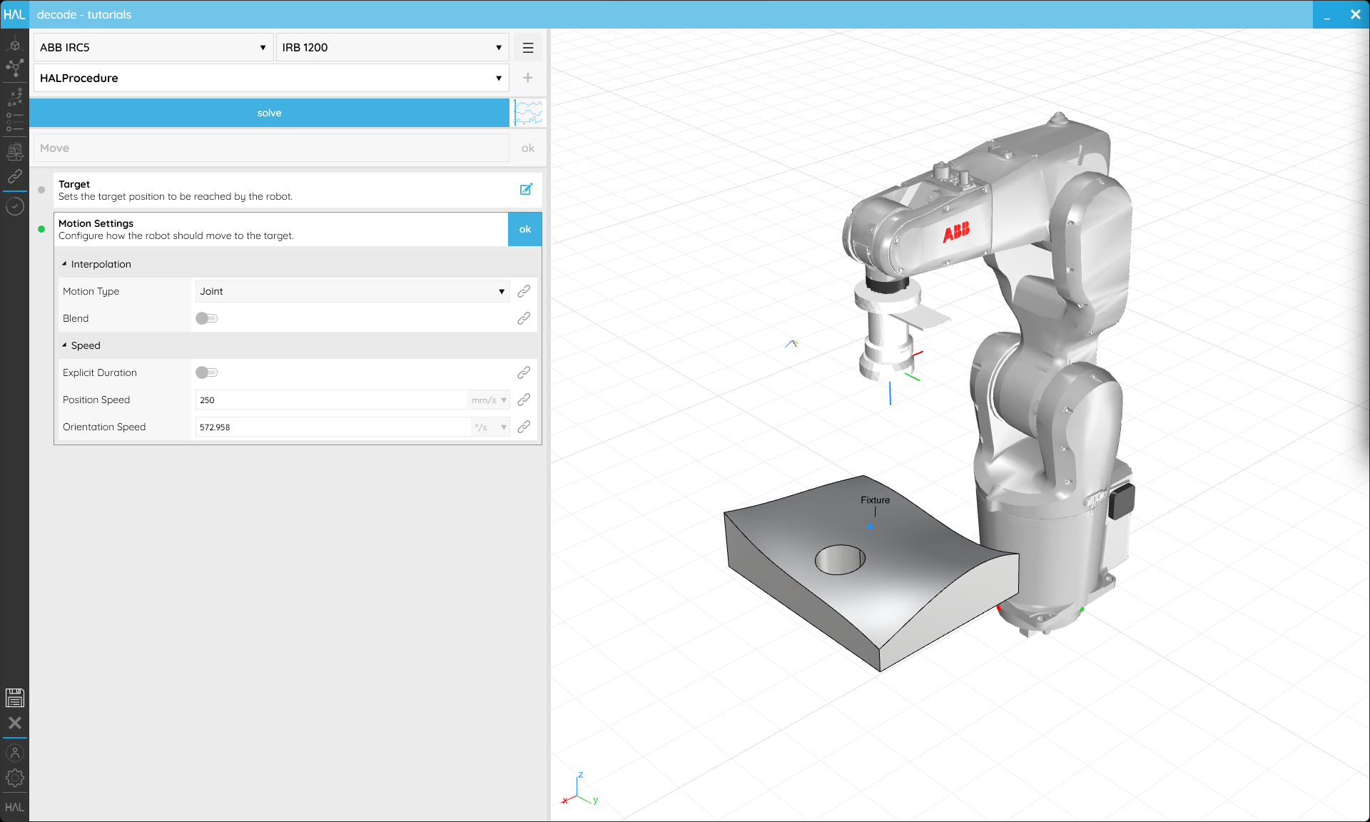
Motion Settings tell the Robot how to get to the Target.
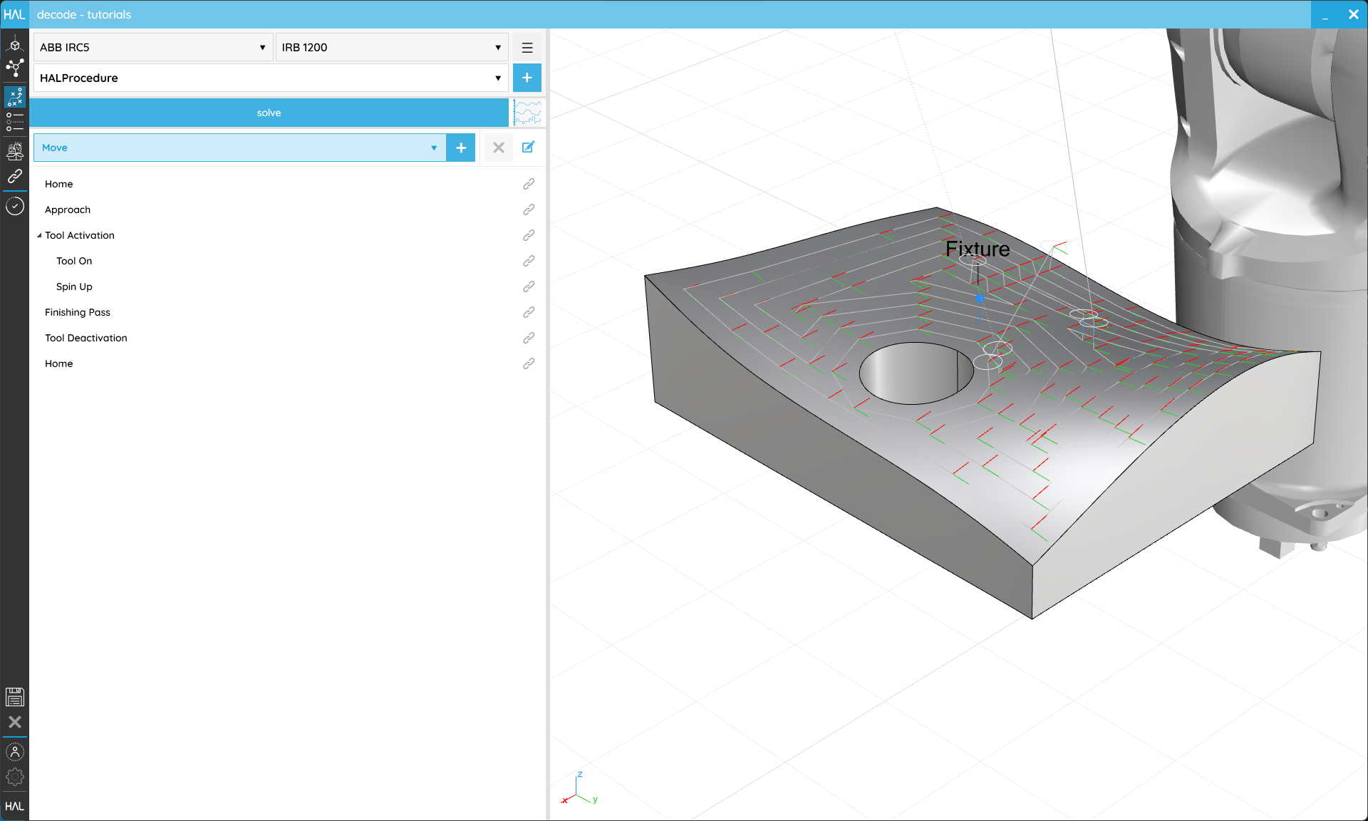
Motion Type controls which path the Robot takes to a Target. In Cartesian mode the TCP moves in a very controlled manner along a straight line or arc. This is probably the easier motion type to visualize but can cause problems when moving between configurations or when trying to optimise cycle times. Moving in Joint space means that each Joint will move from one position to the next without consideration for the position of the TCP. Joint space Moves always end in the same configuration and are not liable to Singularities. It’s often useful to start your Procedures with a Motion in Joint space to ensure your Robot is always initialized to a known position and configuration. It’s worth noting that when using Joint space Motions your Toolpath preview will be dotted until the Procedure is Solved because we can’t know ahead of time exactly where the TCP will go during that Motion. Once Solved, you will see the path your TCP will actually take in space.
Blends sometimes called zones or approximations change how close the Robot needs to get to a Target before moving on to the next. It’s useful to consider your Blends carefully because increasing their size can drastically improve cycle time by allowing the Robot to maintain speed instead of coming to a stop at each Target. Blends are most easily visualized in Position. If we set a 100 mm radius Blend, we can see a circle appear around our Target (unless it’s the very first in a Procedure). This indicates that the Robot will exactly follow our Toolpath until it gets within 100 mm of the Target, at which point it will start to deviate within that circle to keep its speed up and head towards the subsequent Target. It will exactly follow our Toolpath again when it leaves the circle. When we solve our Procedure, we can see the path our TCP will actually take getting close but not actually to all of our Targets.
Speed settings, as the name implies, constrain the speed of your Robot. They can be declared in Cartesian space to directly limit the position or orientation Speed of the TCP. You can also constrain the Speeds of your Robot’s Joints using the second overload or combine the two using the third overload. Please note that not all Robot manufacturers support programmable Joint speed constraints so there may be variations between your simulation and real Robot when they are used.
Acceleration settings constrain the acceleration of your Robot. They function in exactly the same way as the Speeds, constraining Cartesian acceleration, Joint acceleration or both.
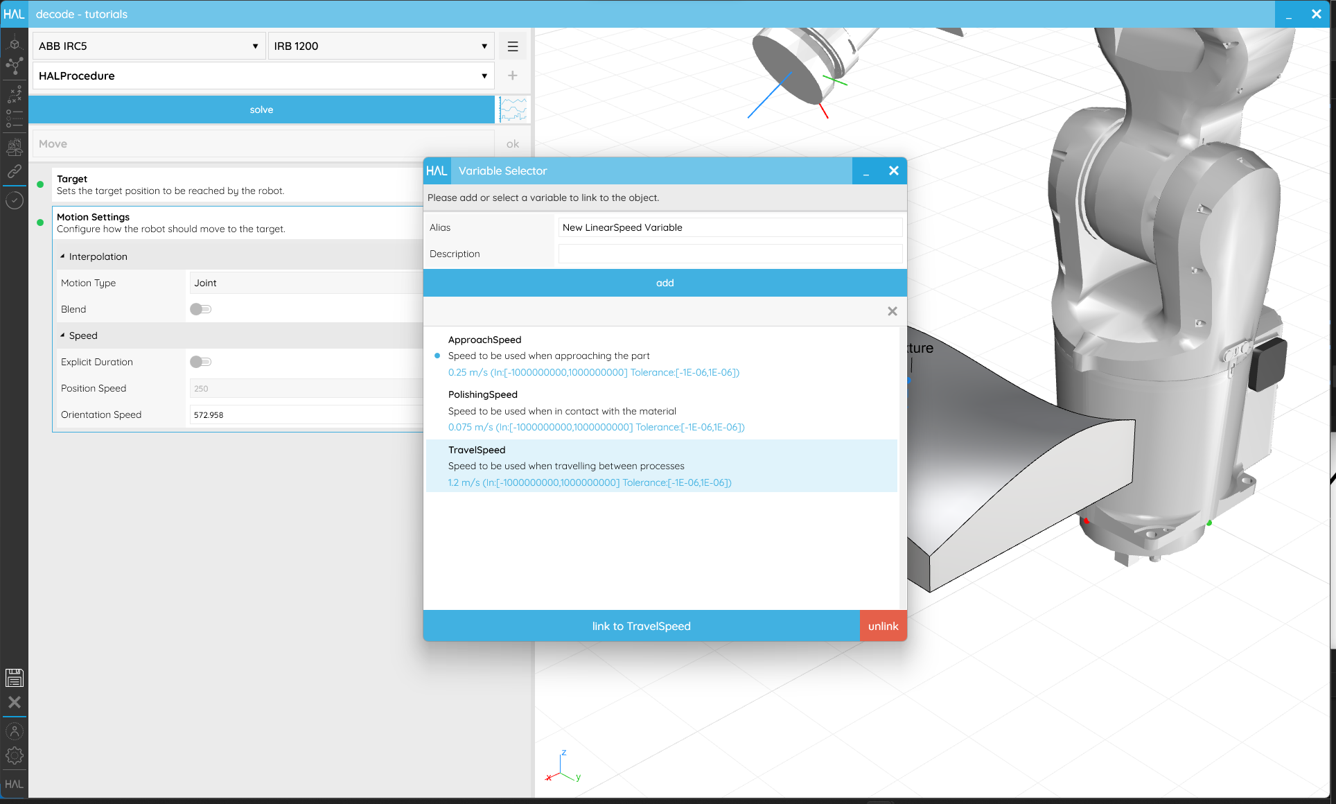
Linking Motion Settings to Variables helps speed up any changes you might need to make in the future and are necessary if you want an operator to be able to change a value.
Once you are happy with the Move’s setup, ensure the name makes it easy to identify and click ok in the upper right corner to return to the Programming screen.
3.2. Wait for a Time
Objective:
In this tutorial we’ll create a Wait Action that pauses Robot execution for a fixed period of time using the HAL Robotics Framework for Grasshopper.
Requirements to follow along:
- HAL Robotics decode installed on a PC. See Installation if you need to install the software.
- An open project
- A Robot in the Scene
- A Controller in the Scene
Background:
In certain scenarios it may be necessary to have your Robot Wait in its current position. This could be because it’s taking a measurement, a Tool is working or simply because something else is happening in the environment. If the time to Wait is a constant, such as the time required for a gripper to open, then a Wait Time Action is a good solution.
How to:
From the Programming screen, select the Group into which you want to add your new Wait, or click anywhere in the white space to clear your current selection. You can always drag and drop Actions onto Groups or in between other Actions to restructure your Procedure later. Either of those states will enable the Item Type selector to list Wait as an option. Click + and you’ll start creating a Wait Action.

Waits allow the Robot to hold in position for a given time.
The default, From Time Creator will allow you to set the time for which the robot should pause. For example, if the Time is set to 2 seconds, when we Simulate the Robot pauses for 2 seconds.
Once you are happy with the Wait’s setup, ensure the name makes it easy to identify and click ok in the upper right corner to return to the Programming screen.
3.3. Set a Signal
Objective:
In this tutorial we’ll change the state of a Signal at runtime in decode.
Requirements to follow along:
- HAL Robotics decode installed on a PC. See Installation if you need to install the software.
- An open project
- A Robot in the Scene
- A Controller in the Scene
- A Signal in your Network. If you don’t have one, see the Create a Signal tutorial for more information.
Background:
Electrical Input and Output (I/O) Signals are used to activate or deactivate Tools, trigger actions on remote machines or pass data between Sensors. The activation of these Signals needs to be triggered at the right time during program execution, something we can do easily with Signal Actions.
How to:
In our previous tutorial, we created a digital output Signal within a Controller and assigned it an appropriate Name.. We now want to change the state of that Signal during the execution of a Procedure. To do so, from the Programming screen, select the Group into which you want to add your new Signal Action, or click anywhere in the white space to clear your current selection. You can always drag and drop Actions onto Groups or in between other Actions to restructure your Procedure later. Either of those states will enable the Item Type selector to list Set Signal as an option. Click + and you’ll start creating a Signal Action.

Signals can be used to activate or deactivate Tools or trigger actions.
You’ll have a Creator for each type of Signal available, e.g. Set Digital Output or Set Analog Output. Within each you will find a list of the relevant Signals in your Network and a Value which should be assigned.
Once you are happy with the Signal Action’s setup, ensure the name makes it easy to identify and click ok in the upper right corner to return to the Programming screen.
3.4. Paths
Objective:
In this tutorial we’ll see how to combine different Procedures to chain sequences using the HAL Robotics Framework for Grasshopper.
Requirements to follow along:
- HAL Robotics decode installed on a PC. See Installation if you need to install the software.
- An open project
- A Robot in the Scene
- A Controller in the Scene
- A CAD Model in the Scene
Background:
Building Procedures Action by Action might be sufficient for some processes but longer Toolpaths can more easily be generated based on some sort of geometry, be that curves, surfaces or meshes. Paths allow exactly that including options for triggering sub-Procedures and jumping between different sections of the Path.
How to:
From the Programming screen, select the Group into which you want to add your new Path, or click anywhere in the white space to clear your current selection. You can always drag and drop Actions onto Groups or in between other Actions to restructure your Procedure later. Either of those states will enable the Item Type selector to list Path as an option. Click + and you’ll start creating a Path.
There are two Creators in Path, Follow Curve and Follow Pattern. The former allows you to select or create curves within your Scene whilst the latter uses curves, surfaces or meshes as input regions that can be filled with a pattern. After that first Curve or Pattern creation section, the Creators then follow exactly the same structure.
Follow Curve
There are lots of different ways to assign curves for the Path to follow, grouped in the Source setting. If you want to follow the edge of a CAD Model you have in your Scene, From Model lets you select that geometry. In the From Model settings you’ll find a selector which allows you to add or remove curves to a collection. Click on select and then the + button in the pop-up to start selecting. Any eligible curves within your model will be highlighted when you hover over them and a single click will add them to the selection. You will see a banner appear above your 3D viewport which has extra information about the next step in the selection process, in this case how to confirm your selection and return to the pop-up. All the curves you selected will be listed here and can be individually removed using the X next to each item, or all cleared with the X next to he + button. You can return to adding or removing curves from the model by clicking the + again. When you’re happy with your selection click ok and you’ll be returned to the Path editor.
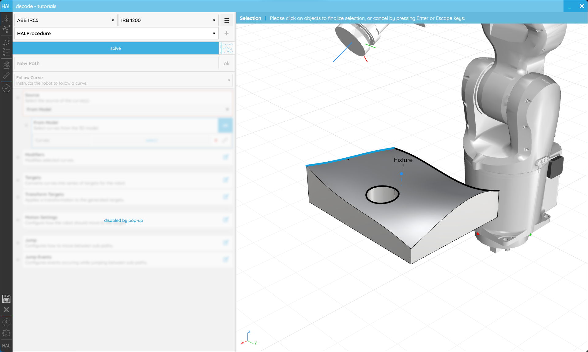
You can select the edges of CAD Models to get your Robots to follow them.
The other Sources allow you to create curves on any CAD Models you have imported. They will all ask you for one or more Host Locations which can be selected on any CAD Model in your Scene, and then a series of relevant Settings. There lots of possibilities here so it’s well worth experimenting with all the options to see what can be achieved. For example from the Spiral Source, setting the Inner Radius and Outer Radius to the same value (maybe even a Variable), and deactivating Flat, will allow you to create a cylindrical spiral at some point(s) on your CAD Model. Or linking your Location(s) to a Variable will allow you to apply several different curves to the same locations.
Complex curves can be generated all over your CAD Models.
The Modifiers then allow you to manipulate those curves, Flipping their direction to control which way the Robot Moves along them, Extending them to over shoot (or using negative values to inset the start and end points). For From Model curves, Join determines whether curves whose ends touch should be considered as a single joined curve or not and Preserve Direction adds a little extra control over when that joining is applied.
Follow Pattern
Both Follow Pattern Creators require some means of defining a Region to work. Planar requires the selection of Boundary curves from a CAD Model. Those can either be independent closed regions or one inside another which will be treated as holes within the outermost region. Non-Planar regions need a surface or mesh from a CAD Model. It’s best to explode complex models into their usable surfaces or meshes in your CAD editor of choice before importing them to make this easier. If you have curves within you CAD Models you can also set these are Boundaries on the Host surfaces but if no Boundaries are specified we’ll the edges of those surfaces in their stead.

Managing the separate surfaces in your original CAD file will make selection easier.
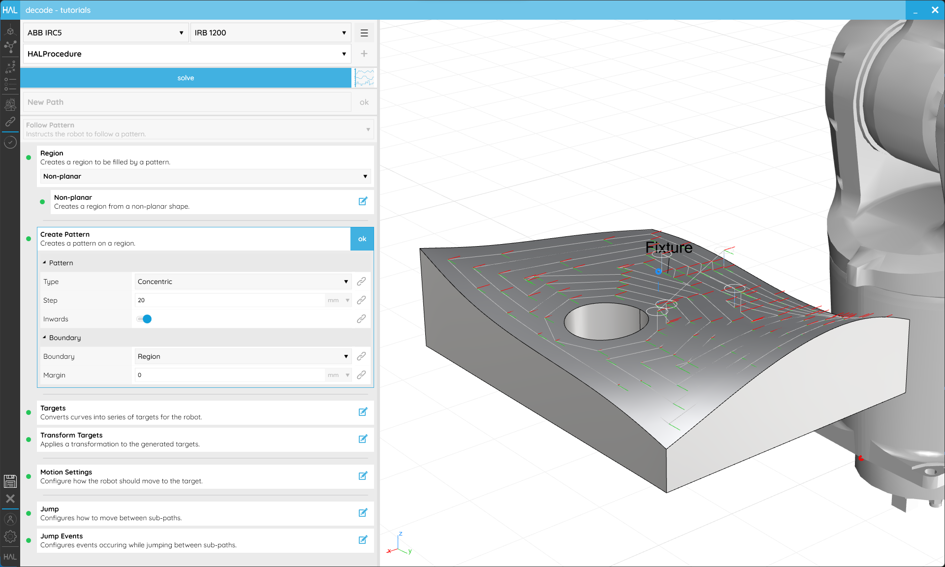
With a Region in place, we can Create a Pattern. The Pattern Type will determine the settings available so, again, it’s worth experimenting to see what they all do. All Pattern Types work well on Planar Regions but we only recommend Concentric or Parallel on Non-Planar Regions.
Entire surfaces, including non-planar ones, can be covered in patterns.
Target Generation
The Targets Step allows you to decide how the geometry we have no selected or created should be subdivided into Moves. The Subdivision Method allows you to decide how the inputs should be approximated whilst the Tolerance allows you to specify how accurately the input should be followed. A larger Tolerance value will allow greater deviation from the input but will result in fewer Targets. Whilst it might seem desirable to make that as low as possible, having too many Targets will generate lots of code and may have a negative impact on Robot performance. The Guide settings allow you to automatically orient your Targets to follow some geometry. For example if you were applying a Pattern to a surface, the Guide would enable you to keep all your Targets normal (perpendicular) to that surface, or if you have selected curves From Model you could keep one of the axes tangent to them (Use Curve As Guide).
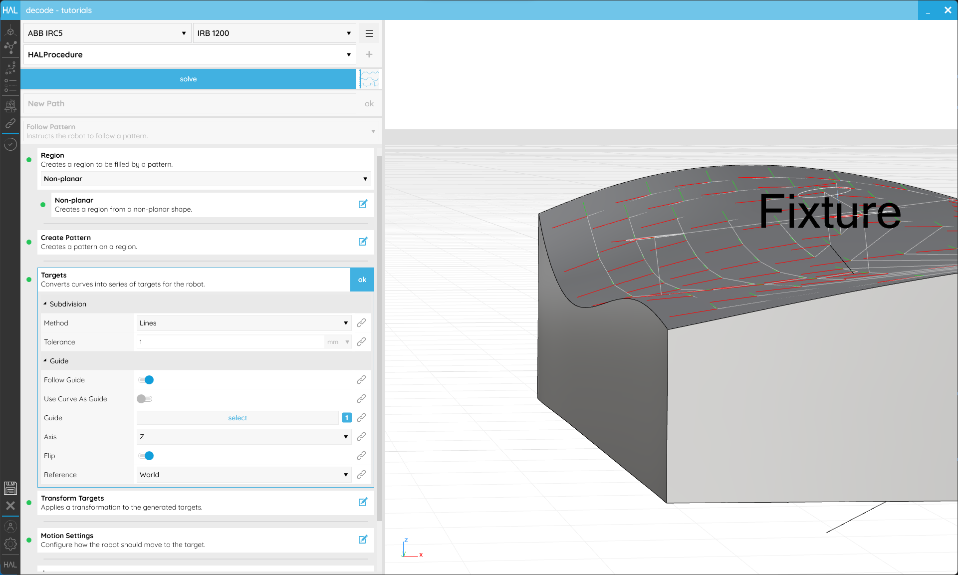
Targets can be aligned to a guide surface to maintain perpendicularity to that surface.
Transform Targets allows you to offset your Targets uniformly. This is applied relative to the Target itself when in Parent or to the World when the Reference is set to the World. If for example you had a pattern across a surface with all of your Targets’ Z-axes facing into that surface, you could moving them all off the surface by 20mm by setting the Position Z value to -20 (minus because it’s in the opposite direction to the Z axis). Or you could rotate all of your Targets around their X-axes by changing the Rotation X value.
![]()
Targets can be offset to create spacing between a Part and the Tool.
Motion
Motion Settings are exactly the same as you will have seen in the Move tutorial.
Jumps
It’s possible that your Path is a single continuous sequence of Targets, but if there are breaks in it Jumps allow you to specify how the Robot should get from the end of one sequence to the start of the next. There are 5 phases to the Jump Step that can all be controlled by the same settings or specified individually.
- Path Entry specifies where the Robot should Move to before the start of the first sequence.
- Path Exit specifies where the Robot should Move to after the end of the last sequence.
- Jump Start specifies where the Robot should Move to after the end of any other sequence.
- Jump End specifies where the Robot should Move to before the start of any other sequence.
- Jump Travel dictates how the Robot Moves between Jump Start and Jump End.
The settings within each of those phases should be familiar by now.
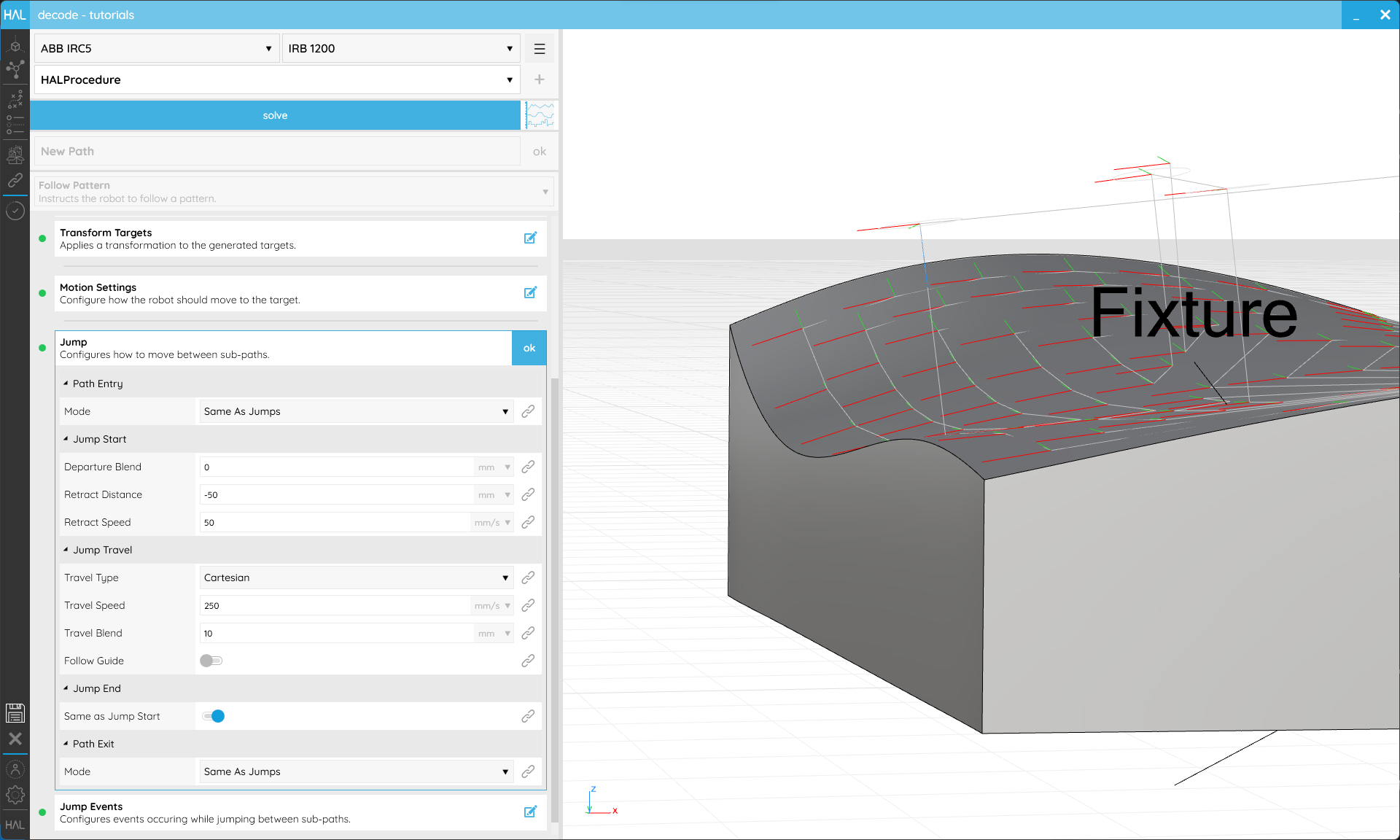
Jumps allow you to control how the Robot gets between segments of your Toolpath.
Jump Events allow you to specify if anything should happen during the Path or its Jumps. That could include activating or deactivating a Tool, triggering a Signal or a Wait. They are all Procedure Calls and therefore need to be created within sub-Procedures. See Structuring Procedures for more details about how those are created.
- Entry On Approach is called at the Path Entry Target.
- Entry On Start is called at the first Target of the first sequence only.
- Jumps On Departure is called at the last Target of each sequence.
- Jumps On Retract is called at the Jump Start point of each sequence.
- Jumps On Travel is called at the Jump End point of each sequence.
- Jumps On Arrival is called at the first Target of each sequence.
- Exit On End is called at the last Target of the last sequence only.
- Exit On Retract is called at the Path Exit Target.
Once you are happy with the Path’s setup, ensure the name makes it easy to identify and click ok in the upper right corner to return to the Programming screen.
3.5. Custom Actions
Objective:
In this tutorial we’ll use a Custom Action to trigger an existing Robot function using decode.
Requirements to follow along:
- HAL Robotics decode installed on a PC. See Installation if you need to install the software.
- An open project
- A Robot in the Scene
- A Controller in the Scene
Background:
When working with a fully integrated Cell or using a Robot with pre-built functionality which isn’t natively supported by the HAL Robotics Framework, you may want add code to your export which calls an existing function in the Controller. We do this using Custom Actions. Common for Custom Actions are opening or closing a gripper, running tool change procedures, starting logging, activating collision boxes, popping up messages to the operator etc.
How to:
From the Programming screen, select the Group into which you want to add your new Custom Action, or click anywhere in the white space to clear your current selection. You can always drag and drop Actions onto Groups or in between other Actions to restructure your Procedure later. Either of those states will enable the Item Type selector to list Custom Action as an option. Click + and you’ll start creating a Custom Action.
The main thing required here is our Code. This should just be the textual representation of the code that you want to export. For example if you wanted to create a pop-up message on an ABB robot you could write TPWrite “Hello Robot”; and that exact line of code will be exported within your program.
Other than the Name, which we recommend always setting, the other setting is Simulation. This allows you to select a Procedure which will change how this Action is simulated but won’t affect how it’s Exported. If you know it’s going to take a second for your gripper to close, for example, you could put a Wait Action in a sub-procedure, assign it to your Simulation and the program will pause when simulated but the code won’t contain any Wait instructions.
Once you are happy with the Custom Action’s setup, ensure the name makes it easy to identify and click ok in the upper right corner to return to the Programming screen.
3.6. Structuring Procedures
Objective:
In this tutorial we’ll see how to simplify your programming by structuring your Procedures in decode.
Requirements to follow along:
- HAL Robotics decode installed on a PC. See Installation if you need to install the software.
- An open project
- A Robot in the Scene
- A Controller in the Scene
Background:
Once your Procedures start to get more complex, you will likely find that certain sequences of Actions are repeated. That could include moving the Robot to a home position, (de)activating a Tool or setting some collection of Signals. Even if those sequences aren’t repeated, it may help the legibility of your Procedures to create a hierarchy to collect Actions into logical groups. We have two ways of doing that in decode, Groups and Procedure Calls.
How to:
From the Programming screen, click in some white space to clear your selection. The Item Type selector should now list Group and Call.
Starting with Group, click + and we’ll enter the Group editor. There are no settings in here other than the name so set one that makes it easy to identify and click ok in the upper right corner to return to the Programming screen. If you then select your new Group you’ll see that any Action can be created within it or existing Actions can be dragged in or out of it. That’s all there is to Groups, they’re there to help you keep Procedures organised.
Groups can help to structure longer Procedures.
Procedure Calls, however, are a little more involved. Before we can use one we’ll need a sub-Procedure to call. In the top right-hand corner you’ll see another + button and a three bar menu (☰). Either of those can be used to add a new Procedure, and the menu can also be used to rename or delete your additional Procedures. As usual give this Procedure an identifiable name, add some Actions and then use the Procedure selector to return to your main Procedure.

Sub-Procedures allow you to create reusable blocks of code.
Once back in your main Procedure’s editor, with a Group or nothing selected, select Call from the Item Type selector and click + to add one. The default Creator has a Configure Step which will allow you to select which Procedure you want to call. This will automatically rename your Call. Once you are happy with the Call’s setup click ok in the upper right corner to return to the Programming screen.

Procedure Calls allow you to reuse sub-Procedures e.g. to deactivate a Tool.
3.7. Validation and Simulation
Objective:
In this tutorial we’ll see how to Simulate our Procedure in decode to ensure it does what we expect.
Requirements to follow along:
- HAL Robotics decode installed on a PC. See Installation if you need to install the software.
- An open project
- A Robot in the Scene
- A Controller in the Scene
- Some Actions in your main Procedure
Background:
There are scenarios in which a single Robot may have access to multiple Tools and the ability to change which Tool is in use at runtime. This could be because, either, the Tool itself has multiple Endpoints or because automatic Tool changing equipment is available in the Cell.
How to:
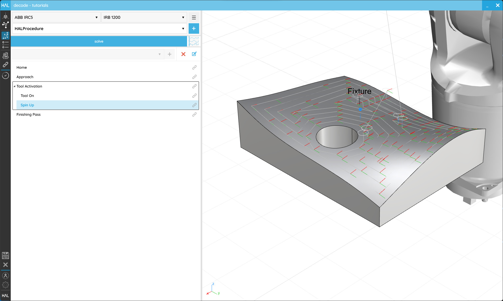
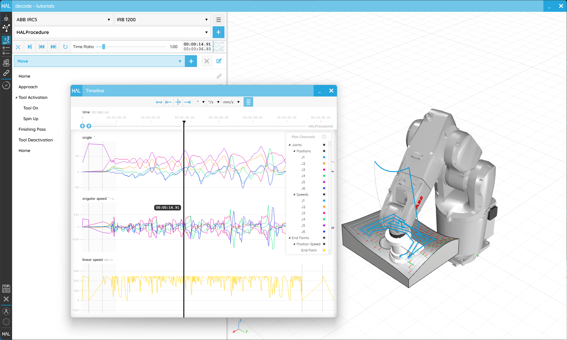
In the Programming screen, between the Procedure selector and the Item Type selector you should see a large blue solve button. Clicking that will run a very fast simulation behind the scenes during which decode will work out how the Robot is going to follow any Toolpaths you’ve created and check for potential issues. If your Procedure is solved that button will be replaced by a simulation control bar with reset, play/pause, next, previous, and loop buttons as well as a time ratio slider to change the playback speed of the simulation. This won’t change the programmed or exported speeds, it’s just like skipping faster or slower through time. On the far right-hand side of that bar is a button with some graphs. That will open the Procedure Timeline which will show you the details of your Robot’s Motion and highlight any issues during the Procedure.
Solving the Procedure triggers the validation of the Procedure and allows its simulation.
Every time you make a change to anything in your Procedure you’ll need to re-solve but we’ll remember what happened last time so subsequent solves will be faster.